Pressure Vessel Engineering and Design
EngRx is composed of a team of pressure equipment experts with extensive design and engineering experience.
Our experience coupled with the industry leading software such as Codeware Compress, Autodesk Inventor, Autodesk Autocad, Mathcad, and Ansys FEA means we can handle all of your vessel design needs.
What we offer:
- Pressure Vessel Engineering and Design of New Equipment
- Repairs and Alterations
- Pressure Vessel Analysis, and Iterations
- Pressure Vessel modifications
- As-Built Drawing Packages utilizing Field Laser Scanning and Design Drafting and Engineering
- CRN application and process management in all Canadian jurisdictions
- Fitness for Service
- Design Based Memoranda (DMB)
- Engineering Design Specifications (EDS)
- Front End Engineering Design (FEED)
- Process Studies and Recommendations for Optimization
What we are recognized for:
- On call engineering services. We are available when you need us.
- Professional engineering to a variety of codes such as; ASME Section VIII Div 1 and Div 2
- Repair and Alterations of special equipment
- Components analyzed by Finite Element Analysis (FEA) and justified within code
- Providing support throughout fabrication, commissioning and the entire life cycle of the equipment
Pressure Vessel and Custom Flange Design Services using COMPRESS Codeware
Providing Advanced Pressure Vessel and Custom Flange Analysis for Clients Globally.
EngRx offers advanced Pressure vessel design, analysis, reverse engineering, and rating using industry recognized software. Our COMPRESS Codeware software capabilities allow for efficient pressure vessel design and engineering that reduces engineering hours while improving reliability and reducing errors.
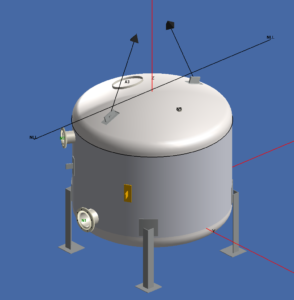
COMPRESS Codeware, is a mainstay in engineering software specially formulated to design and analyze pressure vessels to ASME VIII-Rules for Construction of Pressure Vessels. COMPRESS Codeware can be used to rate pressure vessel designs for storage tanks, boilers, heat exchangers, and process vessels, as well as other systems designed to ASME VIII-1 or 2. COMPRESS Codeware can also use previous Code years from 1995 to present as well as previous building code from 1980 to present.
Our team of Engineers and their expertise can help you to determine the maximum safe operating pressure and temperature for your proposed and existing systems, Conduct Stress analysis, specify Non-Destructive Testing, determine minimum design temperature (MDMT), and determine Welding requirements.
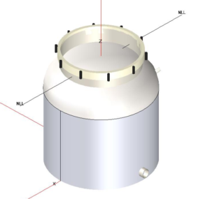
Typical Capabilities of COMPRESS Codeware are:
- ASME VIII-1 and ASME VIII-2 Class 1 and 2 Calculations for Internal and External Pressure
- Pressure Vessel Fatigue Assessment
- Considering failure due to cyclical stresses using ASME VIII-2 Fatigue Screening
- Detailed Nozzle Design
- Calculating Hillside Nozzle Intersections
- Detailed Nozzle opening drawings
- Calculating nozzle support requirements
- UG-37 Nozzle Design Configurations
- “Q-lip” style nozzles
- UG-36, UG-37, UG-45, and UW-16 Considerations
- Economical Nozzle Design Using ASME Appendix 46
- Studding Outlets
- Nozzle Connections of B16.11 couplings, B16.9 elbows, reducers, pipe caps, tees, pipe extensions and Appendix 2 or B16.5/B16.47 flanges
- UG-37 Overlapping Limits of Reinforcement
- Radial, Tilted or Hillside (Offset), additional Code provisions required for Tilted and Hillside nozzles are calculated automatically in COMPRESS Codeware
- Determining MDMT Rating, UCS-66, and UHA-51, with Impact Test Requirements and Exemptions
- Reliably Prevents Brittle Fracture Failures
- ASME PCC-1 Appendix O Assembly Bolt Stress Calculations
- Simple approach, determine bolt stress based on the target gasket stress
- Joint approach, determine bolt stress based on Gasket seat stress and material allowable stresses
- Design with a Library of ASME B16 Fittings
- ASME B16.5/B16.47 standard flanges and blinds
- ASME B16.9 elbows, conical reducers, and support skirt openings
- ASME B16.9 pipe cap heads with attached nozzles
- ASME B16.20 and B16.21 standard gasket dimensions
- Elliptical manways
- Vertical and Horizontal Vessel Design with UG-22 Loads Determination
- Vessel Structural Support Design with Consideration to Building Codes NBC, ASCE and IBC
- Support skirts with openings and nozzle extensions
- Saddles (Zick analysis)
- Braced and un-braced legs
- Support lugs
- Base rings and compression rings
- Anchor chairs and anchor bolts
- Liquid Static Head Determinations
- Automatically accounts for any nozzle connections.
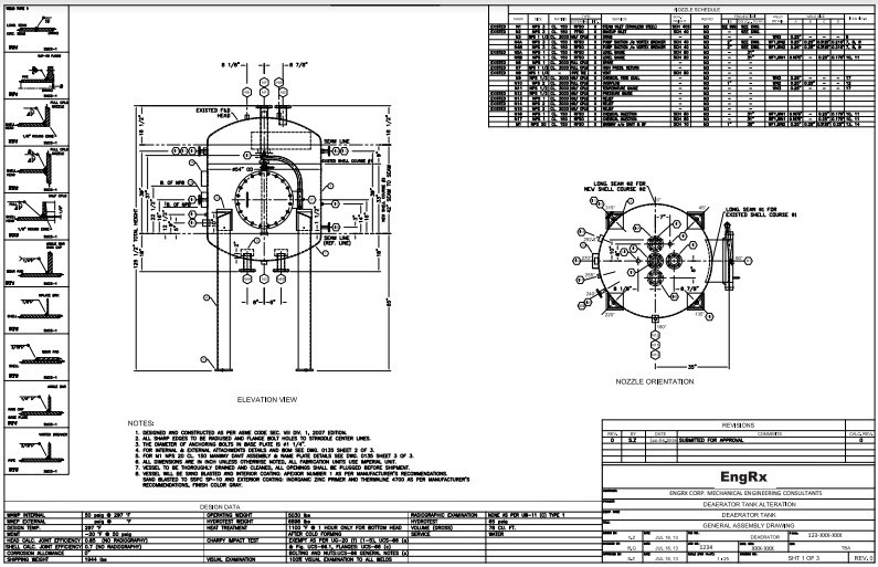
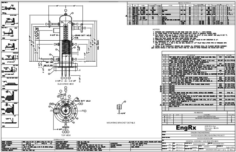
- Solid Modeling and Drawings
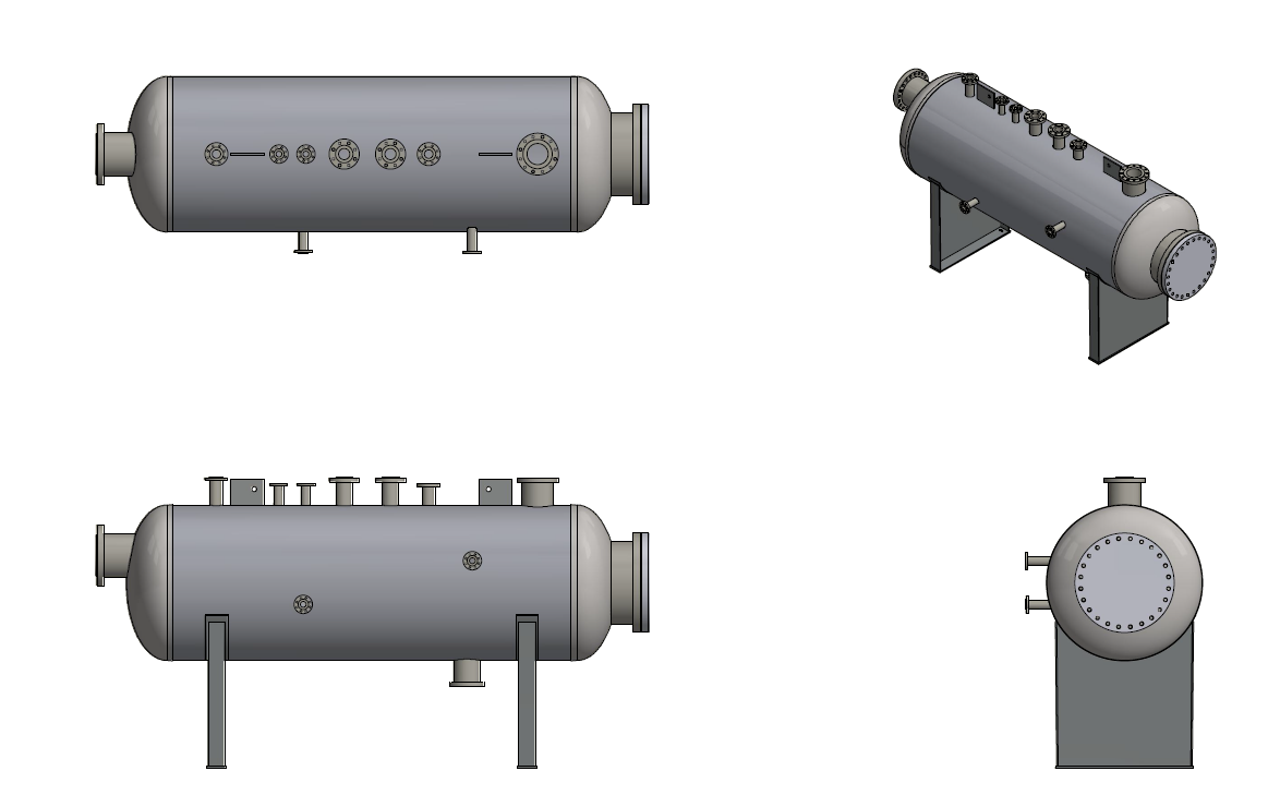
- Special Inventor integrated Codeware interface allows EngRx to develop Inventor models quickly and effectively from COMPRESS Codeware native files, this allows us to quickly produce detailed drawings when necessary.
- Quickly creates Inventor or Solidworks models from COMPRESS Codeware pressure vessels. These models take advantage of Inventor and Solidworks features such as Mates and Sheet Metal.
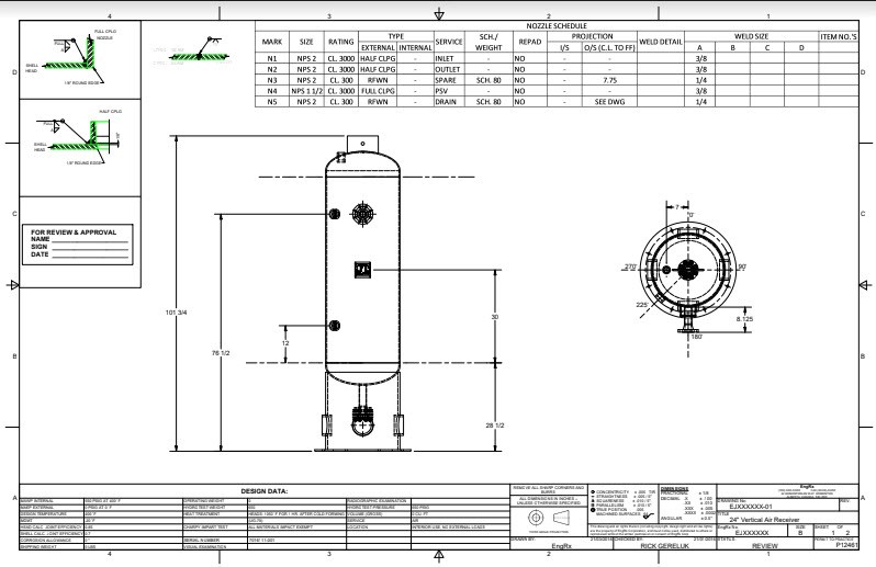
- Manufacturing Drawings
- Weld Maps and Weld Details
- Sheet Metal Drawings
- CAD models for your Plant Layout
- Design of Lift Lugs (ASME B30.20), Ears, Trunnions and Skirt Struts
- Lifting and Rigging Analysis
- Bending moment, shear stress and bending stress diagram
- Perform a local stress analysis on clips and lugs using WRC 107 / WRC 537
- Design of Pressure Vessel Internals and Attachments
- PDF Reports with Summary of Results and Calculation Methodology
- Hydrotest Stress Calculations
- Component stress checks
- Formed head bucking check
- Test medium weight considerations
- RT Marking and Radiography Summary
- Bill of Materials
- Static Head Calculations
- Automatically considers nozzles and liquid level
- Internal and External Corrosion Allowance
- Design of Shipping Transportation Saddles
- Consider applied shipping loads
- Wind and Seismic
- Road, Rail, Barge and Ocean
- Shell Thicknesses Optimization
- Vessel Dry Weight and Flooded Weight Determination
- Weld Sizing and Selection
- Cladding per UCL-23
- Lining – UCL-23(a)
- Integral Cladding – UCL-23(b) without thickness credit
- Integral Cladding / Weld metal overlay – UCL -23(c) with thickness credit
- Conventional and Half Pipe Jacketing
- ASME UG-28 and Appendix 9
- ASME VIII-1, Appendix EE and ASME VIII-2, Part 4.11
- Cost Estimation
- Generates costed bill of materials in Excel Automatically
- Generates costed nozzle cut lists broken down by pipe size and length
- Generates costed weld length and type list
- Calculates cost of impact testing, PWHT, x-ray and hydrogen service
- Automatically generate National Board Inspection Code Report Forms
- Manufacturer’s Data Report Forms
- Manufacturer’s Certificate of Compliance
- National Board Inspection Code Report of Repair
- National Board Inspection Code Report of Alteration
- Nameplate and mounting bracket design
Custom Flange Design:
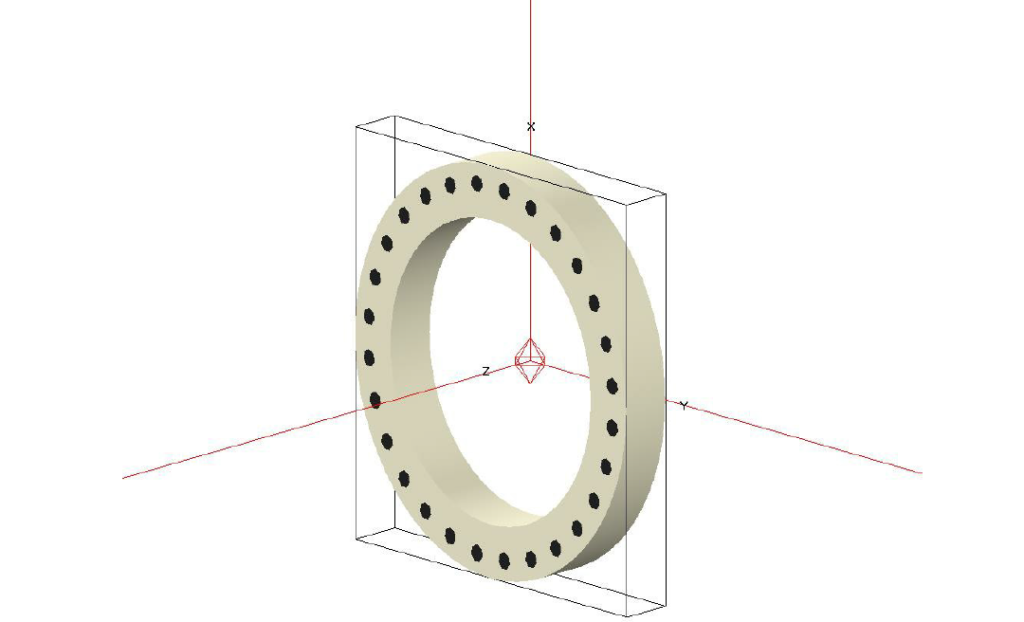
EngRx uses COMPRESS Codeware to design and rate custom flanges for your next project.
When Standard ASME B16.5 and 16.47 rated flanges will not meet your applications requirements EngRx will design custom ASME Appendix 2 flange configurations to best suit your needs. COMPRESS Codeware aids in the design of appendix 2 flanges with a flange design wizard which makes flange design quick and dependable as opposed to the typically engineering hours intense work of flange design. COMPRESS Codeware can also be used for modification to existing ASME B16.5 and 16.47 flanges, such as reductions in thickness, diameter or increase in bolting size.
Additional Consideration of COMPRESS Codeware for Effective Reliable Flange Design:
- Custom designed flange pairs with mating flange bolt loads designed in accordance with ASME VIII-1, Appendix 2-5(a)(2) for your heat exchangers or other pressure vessel applications
- Bolting loads from gasket seating
- Appendix 2 Flange maximum allowable working pressure iterations
- External Flange Loadings and Piping Loads. COMPRESS Codeware allows for the consideration of additional applied external loadings
- Wind and Seismic Loadings on Appendix 2 Flanges
- Gravity forces on Appendix 2 Flanges from supported weight
- User specified forces and moments.
- UG-44 external loadings on B16.5/16.47 rated flanges
- Discontinuity stresses calculations for Flanges without knuckles or flare radii
- UG-44 external loadings on B16.5/16.47 rated flanges
- Bolted Joint Analysis per ASME PCC-1 Appendix O using simple approach to determine bolt stress based on target gasket stress or the joint approach which considers gasket seating stress, gasket compressive strength, bolt allowable stress and flange allowable stress
- Custom ASME VIII-1, Appendix Y Flanges
- UG-34 Bolted Covers, designed to accommodate B16.5/16.47 rated flanges or Custom designed Appendix 2 or Appendix Y Flanges
COMPRESS Codeware Aided FEA Analysis:
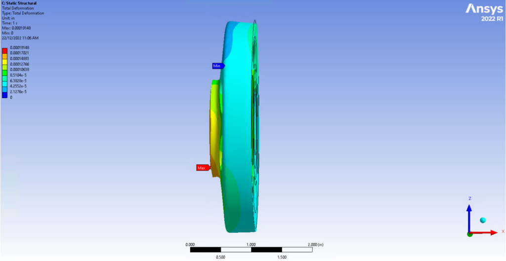
Some applications can require the use of additional special FEA analysis on custom flanges in accordance with U-2(g). EngRx is more than capable of supporting these application with years of expertise in FEA analysis, made even simpler and more cost effective with COMPRESS Codeware instant 3D modeling. This allows for quick solid models that can then be exported into ANSYS FEA Software and be used to conduct special FEA analysis by EngRx. This removes front end work of labour intense modeling and eliminates potential for errors.
WRC 107 and WRC 537 to Analyze ASME VIII-1, UG-22 Pipping Loads on Nozzles and Flanges:
COMPRESS Codeware has the added capability to analyze ASME VIII-1, UG-22 Pipping Loads using the methods of Welding Research Council Bulletins 107 and 537 for local stresses in spherical and cylindrical shells. This analysis can be used to quickly and effectively iterate nozzle and flange design based on analysis results.
UG-44 to Analyze ASME VIII-1, UG-22 Pipping Loads on B16.5/16.47 Rated Flanges:
COMPRESS Codeware can effectively utilize the methods outlined in UG-44 to analyze ASME VIII-1, UG-22 Pipping loads on B16.5/16.47 rated flanges, implementing a Moment Correction factor which produced more economical designs then those produced by WRC 537.
Using COMPRESS Codeware and other engineering resources, EngRx can provide your company with complete engineering design calculations, construction and assembly drawings, solid models of assemblies and components and design registration for your ASME VIII-1 or ASME VIII-2 projects.

